How to install a fluid Switch Slide Rail (for retrofitting existing Shower)
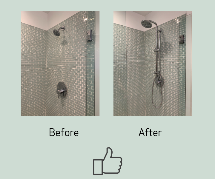
fluid Switch is a retrofit shower bar that is used both for new installations or to easily add a Hand Shower and slide rail to an existing shower installation without having to damage walls or change behind the wall plumbing. This article details how to retrofit an existing shower. (Note: for full installation instructions with labelled parts diagram are Click Here, and full installation video is below):
Before you Start!
If you take a few minutes before you start to look at where you want to install fluid Switch, you won't run in to any unforeseen problems!
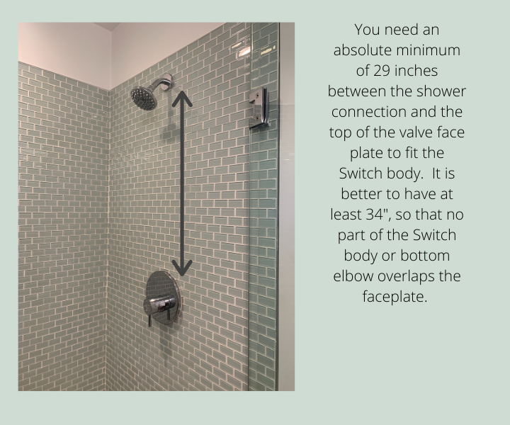
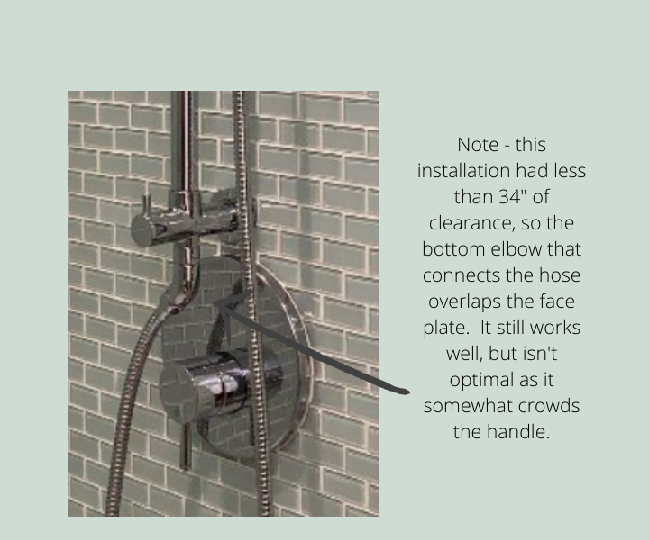
- Measure the distance from the shower head to the top of the valve cover plate. You need a minimum of 29 inches of clearance for the Switch Slide Rail to fit. It's better to have 34", (see below for details).
- Make sure that you have enough height! The new shower arm will extend a bit higher than your old shower head. You need at least 6" clearance from the shower head connection to the ceiling for the 8" shower arm and a minimum of 8" clearance for the 8"-TALL shower arm or the 16" shower arm.
- Have a look at the hole cut in the finished wall where the shower arm is installed. The escutcheons (cover plates) included measure 50 mm (a little under 2"). If the hole in your wall is larger than this, you can order optional larger escutcheons. 65 mm (2.5")-Part #FP6007049.
- Thin walls: If you have walls under 1/2" thick you can still use Switch, but it is very important to remember that Switch is a Shower Slide rail. It is NOT intended to be a Grab Bar and will not be sufficient to support a person. Using any slide rail as a Grab Bar is very dangerous and could result in severe injury and/or damage to your wall.
- Switch works with standard North American plumbing fitting sizes, (1/2" NPT). If you have a European or other plumbing sizing installed, you may have to use an adapter at the connection.
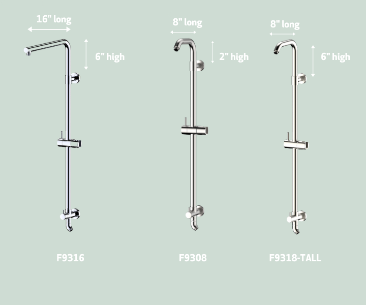
- Switch is available with either an 8" or 8" TALL arm (for a fixed shower head or a 6" rain shower style shower head) OR a 16" arm for a standard 8" rain shower head. You will need to choose when you order which style best suits your needs. (Remember - you can change your mind later! If you choose one style and decide to change, you can order the alternate shower arm and change it out. Switch is all about flexibility!)
Tools you will need to complete this project:
- 2.5 mm )3/32"_ Allen Wrench (supplied)
- 8 mm (5/16") Allen Wrench (not supplied)
- Teflon tape (not supplied)
- Small flat head screwdriver (not supplied)
- Small Phillips screwdriver (not supplied)
- Adjustable wrench (not supplied)
OPTIONAL - Drill with 1/4" and 1/2" bit (If you choose to install by drilling hole in to tile to secure bottom of slide rail to shower wall. Alternately you can use the included tube of glue. Note - do not substitute with alternative glue. This is a specialty glue intended for this application.
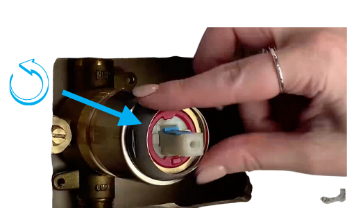
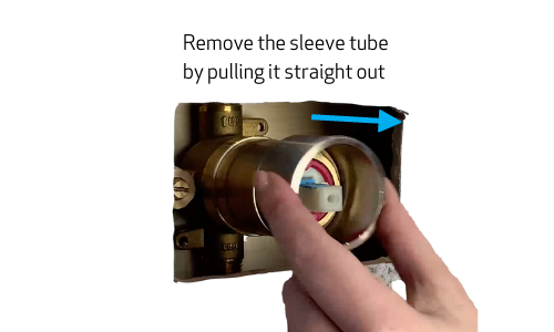
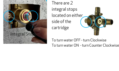
Shut off water supply, either by shutting off water to the house or if available, by turning integral stops at the valve
Remove existing shower head and shower arm with a crescent wrench.
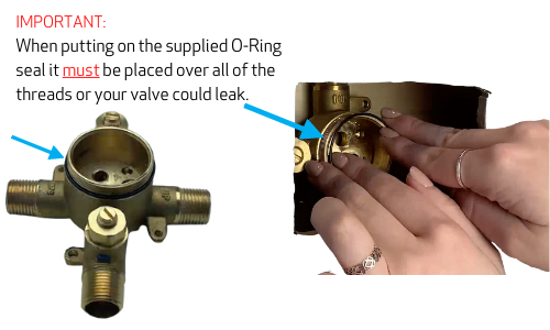
Apply Teflon tape to the end of the included fluid Speed Connector. Insert Speed Connector into the drop elbow behind the wall, (not supplied; this is the fitting that previously would have connected to the shower arm) and tighten with a 5/16" (8 mm) Allen wrench.
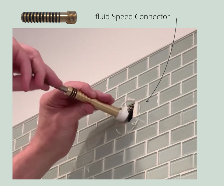
Note: the exposed Speed Connector must extend outside the finished wall between 1" (25mm) and 1-3/4" (45 mm). If the Speed Connector is shorter than the required 1" a 1/2" NPT male to female brass fitting can be purchased and added to extend it, or there is a longer 110 mm Speed Connector available for purchase. Part # FP8001023. If it is too long, you can cut the Speed Connector with a hacksaw above one of the O-ring connections. (Note: You must have at least 3 O-rings remaining to ensure a water tight fit.)
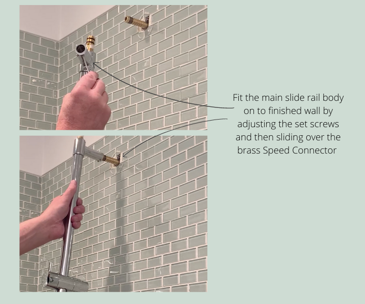
Connect the main body of the slide rail by pushing the top connection over the brass Speed Connector.
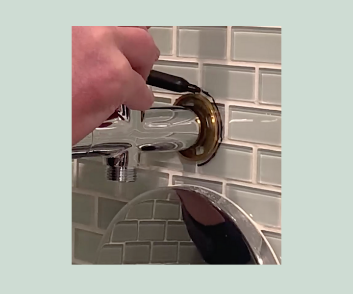
Now it's time to figure out where to position the bottom mounting plate. You will want to make sure that this is level with the top connector. Once you figure out the best placement, use a pencil or non permanent market to mark the locations of the 4 holes in the mounting plate, or if you are using the glue method you can simply draw a circle around the mounting plate to mark the position. Remove the mounting plate from the bottom connection assembly.
Here is where the optional mounting decision comes in. You can either connect the bottom of the Switch slide rain by inserting with screws OR you can use the special glue included with the Switch. This is completely your choice. The video above shows the installation on glass tile, so it was advisable to use the included glue, as the chance of breaking the tile by drilling was quite high. If you are comfortable drilling in to the tile, by all means choose the drilling option, but remember, we are unable to take responsibility for this any damage caused.
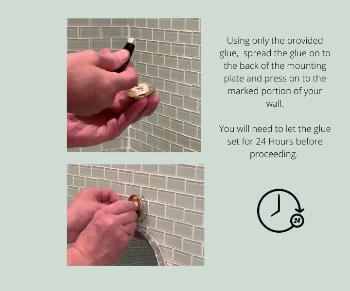
If using the glue option: Spread about (how much) glue on the back of the mounting plate and press on to the marked portion of the wall. NOTE: You will need to leave the glue to set for 24 hours to ensure maximum adhesion.
If drilling:
Solid Wall Option: Drill 4 1/4" (5.5 mm) holes into the finished wall, (from the markings you created in the step above). Insert the supplied plastic anchors into the drilled holes. Securely attach the mounting bracket into the finished wall with the suppled screws and tighten with a Phillips screwdriver.
Hollow Wall Option: Use the suppled spring toggle bolts. Drill either two - 1/2" (11 mm) holes into the finished wall. Assemble the toggle anchor and screw with the mounting bracket. Insert the spring toggle anchor through the holes and tighten the screws with a Phillips screwdriver. Note: use two spring toggle anchors in opposite directions to avoid interference with each other behind the wall.
Next, make sure that both the round escutcheons are attached on the main body of the Switch at the top and bottom connection. If not, remove the set screws by using the supplied 3/32" (2.5mm) Allen wrench and then slide the round escutcheons over the top and bottom connections.
Now, fit the main body of the Switch over the brass Speed Connector at the top and to the mounting plate at the bottom connection.
Tighten the set screw with the suppled 3/32" (2.5mm) Allen wrench to secure the main body assembly.
Make sure that the hole located on the bottom of the shower arm is aligned with the hole on the plastic ring on the top of the brass connector as shown below.
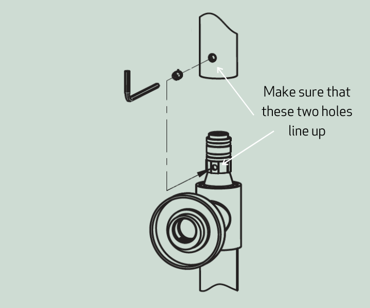
Push the shower arm onto the top brass connector of the main body of the Switch assembly. When it is fully inserted, it should lock into place.
Tighten the set screw on the shower arm with the suppled 3/32" (2.5mm) Allen wrench. It is helpful to swing the shower arm over to start, so that you can more easily access the set screw. Once it starts getting tight, position the shower arm to the place you want it and tighten the rest of the way. If you would like the shower arm to swivel, back off the set screw by half to one full turn.
Next you will want to attach the elbow at the bottom of the Switch main body. First add teflon tape to the elbow and then screw it onto the bottom outlet of the body. Turn the outlet to the position you would like, keeping in mind that the main purpose of this elbow is to position the flex hose so sit around and not over top of the valve cover and handle. So, it is best to position it in the opposite direction of the side where the Hand Held shower wand will sit on the Switch body. Tighten the elbow with an adjustable wrench.
This finishes the installation of the Switch unit itself, but you will still need to attach the optional components that you have chosen.
Attach the shower head by placing teflon tape onto the end of the shower arm and turning the shower head directly on to the shower arm.
Attach the flexible hose for the hand held shower directly to the elbow at the bottom of the Switch body. Then, attach the chosen hand held shower wand to the end of the flexible hose and rest in the holder on the side of the Switch unit.
Turn the water supply back on
You are done and ready to enjoy your enhanced shower system!